
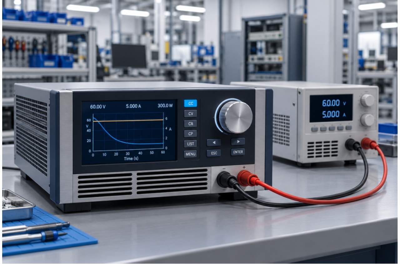
A DC electronic load looks simple from the outside. You connect a power supply to its input terminals, set a current or resistance value, and it sinks power. The voltage drops, the current flows, and you can measure whether the supply holds regulation. That’s the basic job, and it hasn’t changed in decades.
But the DC electronic loads used in modern production testing are nothing like the resistor banks they’ve replaced. A current-generation programmable DC electronic load operates in multiple modes — constant current, constant voltage, constant power, and constant resistance. It can switch between modes automatically during a test sequence. It can simulate a battery discharging, a motor starting, or a capacitor bank charging. And it records voltage, current, and power measurements at sampling rates fast enough to catch microsecond-level transients.
Operating modes and when to use each one
Constant current (CC) mode is the most commonly used. The load draws a fixed current regardless of the input voltage, within its compliance range. This is how you test a power supply’s load regulation — set the current to 50% of rated output, measure the voltage, then step to 100% and measure again. The difference tells you how well the supply holds its output voltage under varying load.
Constant voltage (CV) mode works differently. The load forces the input voltage to a set value by adjusting the current it draws. This is useful for testing current-limited power supplies and battery charging circuits. If you’re testing a constant-current LED driver, for example, setting the load to CV mode at the driver’s rated output voltage lets you verify that the driver delivers its specified current.
Constant power (CP) mode makes the load draw a fixed wattage. As the input voltage drops, the current increases to maintain the power setpoint. This mode is important for testing power supplies under their maximum rated load condition, especially when the supply’s output voltage droops under heavy load.
Constant resistance (CR) mode simulates a fixed resistive load. Unlike CC mode, where the current is set directly, CR mode lets the current vary with the applied voltage according to Ohm’s law. This is the most realistic simulation for many real-world loads — heaters, incandescent lamps, and DC motors all behave as resistive loads.
Modern programmable loads also support combined modes, like CC+CV, where the load operates in constant current until the voltage drops to a threshold, then switches to constant voltage. This is essential for battery discharge testing, where you want to draw a fixed current until the battery reaches its cutoff voltage.
Dynamic testing and transient response
A power supply’s static performance — its voltage at 50% load, for example — only tells part of the story. The more important metric is how the supply behaves when the load changes suddenly. A server power supply that regulates perfectly at steady state but droops 500 mV when a storage array spins up its drives is a power supply that will cause system resets.
Dynamic testing with a DC electronic load involves programming the load to switch between two current levels at a defined frequency and slew rate. A typical test might cycle between 25% and 75% of rated current at 1 kHz with a slew rate of 1 A/μs. The oscilloscope captures the output voltage waveform, and measurements of overshoot, undershoot, and recovery time tell you whether the supply’s control loop is stable.
The electronic load products in Jettest’s ecosystem are designed with this testing in mind. They support programmable slew rates and arbitrary waveform generation for dynamic load profiles. When integrated into an automated test line, the load executes synchronized test sequences — step load, pulse load, and sweep — while the data acquisition system records the power supply’s response.
For manufacturers of EV chargers and energy storage systems, dynamic testing with electronic loads is non-negotiable. These applications involve rapid load changes during normal operation — a fast-charging station that suddenly drops from 350 kW to zero when a vehicle disconnects, or an inverter that switches from grid-tied to island mode in milliseconds. The power supply or converter feeding these loads must handle the transition without tripping protection circuits or going out of regulation.
Battery discharge simulation
One of the most valuable applications for a programmable DC electronic load is battery discharge testing. In CC mode, the load draws a constant current from the battery while the voltage is monitored. The test records the discharge time, the voltage curve, and the total capacity delivered before the battery reaches its cutoff voltage.
This isn’t just a pass/fail test. The voltage curve during discharge reveals a lot about the battery’s health and quality. A fresh lithium-ion cell shows a characteristic plateau around 3.6 to 3.7 V for most of the discharge, with a sharp drop at the end. A cell with internal resistance problems shows a steeper voltage drop from the start. A cell with capacity degradation reaches the cutoff voltage earlier than expected.
In production, these tests are run on battery packs, modules, and cells at various stages of assembly. The DC electronic load is the core instrument for the discharge portion of the charge-discharge cycle, and its accuracy determines whether the battery’s rated capacity is verified or not.
Beyond simple constant-current discharge, modern loads can simulate complex discharge profiles that match real-world usage patterns. An electric vehicle battery pack, for example, doesn’t discharge at a constant rate. It sees pulses of high current during acceleration, lower current during cruising, and regenerative charging during braking. A programmable load can replicate this profile in the lab, providing a more accurate assessment of how the battery will perform in actual use.
Selection criteria for production loads
Choosing a DC electronic load for production testing requires considering several factors beyond power rating and voltage range. Accuracy and measurement resolution determine whether the load can detect small deviations in performance. A load with 0.1% accuracy is adequate for general power supply testing, but battery capacity testing requires better than 0.05% accuracy on current measurement.
Slew rate determines how fast the load can change its current draw. For testing the transient response of modern power supplies with fast control loops, a slew rate of at least 1 A/μs is recommended. For high-current applications, some loads offer slew rates above 10 A/μs.
The number of channels matters in production. A single-channel load tests one unit at a time. A multi-channel load tests multiple units simultaneously, increasing throughput. Some manufacturers use a matrix of single-channel loads, but multi-channel instruments offer better synchronization between channels and a smaller physical footprint.
Communication protocol compatibility is critical for automated production. The load must speak the same protocol as the test system controller. LAN (TCP/IP) with SCPI commands is the most common in modern production lines, followed by GPIB in older installations and USB in benchtop applications.
Communication and automation
A DC electronic load in a production environment is never operated alone. It’s controlled by the test system’s software over a standard interface — GPIB, USB, LAN, or RS-232. The test program sets the operating mode and parameters, initiates the test, reads the measurements, and decides pass or fail based on programmed limits.
The communication protocol matters because it determines test speed. A load that updates its setpoint via LAN in 10 ms can run dynamic sequences much faster than one that takes 50 ms over RS-232. When you’re testing hundreds of units per shift, those milliseconds add up.
Modern loads also support data logging at high sampling rates. Instead of reporting just the final voltage and current, they stream measurement data to the test system throughout the test. This allows engineers to analyze the test waveform after the fact and detect anomalies that an average reading would miss.
For manufacturers looking to integrate DC electronic loads into their production lines, the fully automatic test and burn-in line from Jettest handles the load integration at the system level. The load, the measurement instruments, and the material handling are all coordinated by the line controller, so operators don’t need to configure individual instruments.
Matching the load to the line
The DC electronic load is the workhorse of power supply testing. Its ability to simulate real-world loads, capture dynamic behavior, and integrate with automated production systems makes it indispensable for any manufacturer that needs to validate power supply performance thoroughly and efficiently. The choice of load — single-channel or multi-channel, regenerative or conventional, LAN or GPIB — depends on the application, but the principle is the same: test the supply the way it will be used.
Practical integration examples
In a typical power supply production line, the DC electronic load is part of the final test station. The conveyor brings the assembled unit to the station, where automatic probes connect to the output terminals. The test system commands the load to cycle through its operating modes — CC mode for load regulation, CR mode for startup behavior, and dynamic mode for transient response — while an integrated data acquisition system records the voltage, current, and power readings. The entire sequence takes 15 to 30 seconds per unit, depending on the number of test points.
For manufacturers using the fully automatic PCBA ICT/FCT test system from Jettest, the DC electronic load is integrated at the FCT stage. The load applies the programmed test profile while the system measures output parameters and compares them against the specification limits stored in the test program. Units that pass are routed to the burn-in station. Units that fail are flagged with the specific test parameter that exceeded the limit, making diagnosis faster and more accurate.