
These escapes happen because functional testing — even thorough functional testing — doesn’t check every node on the board. It checks whether the assembled product works as a system. If a wrong-value resistor happens to be within the tolerance band that still allows the power supply to regulate, functional test won’t catch it. In-circuit testing exists specifically to close that gap.
What in-circuit testing actually checks
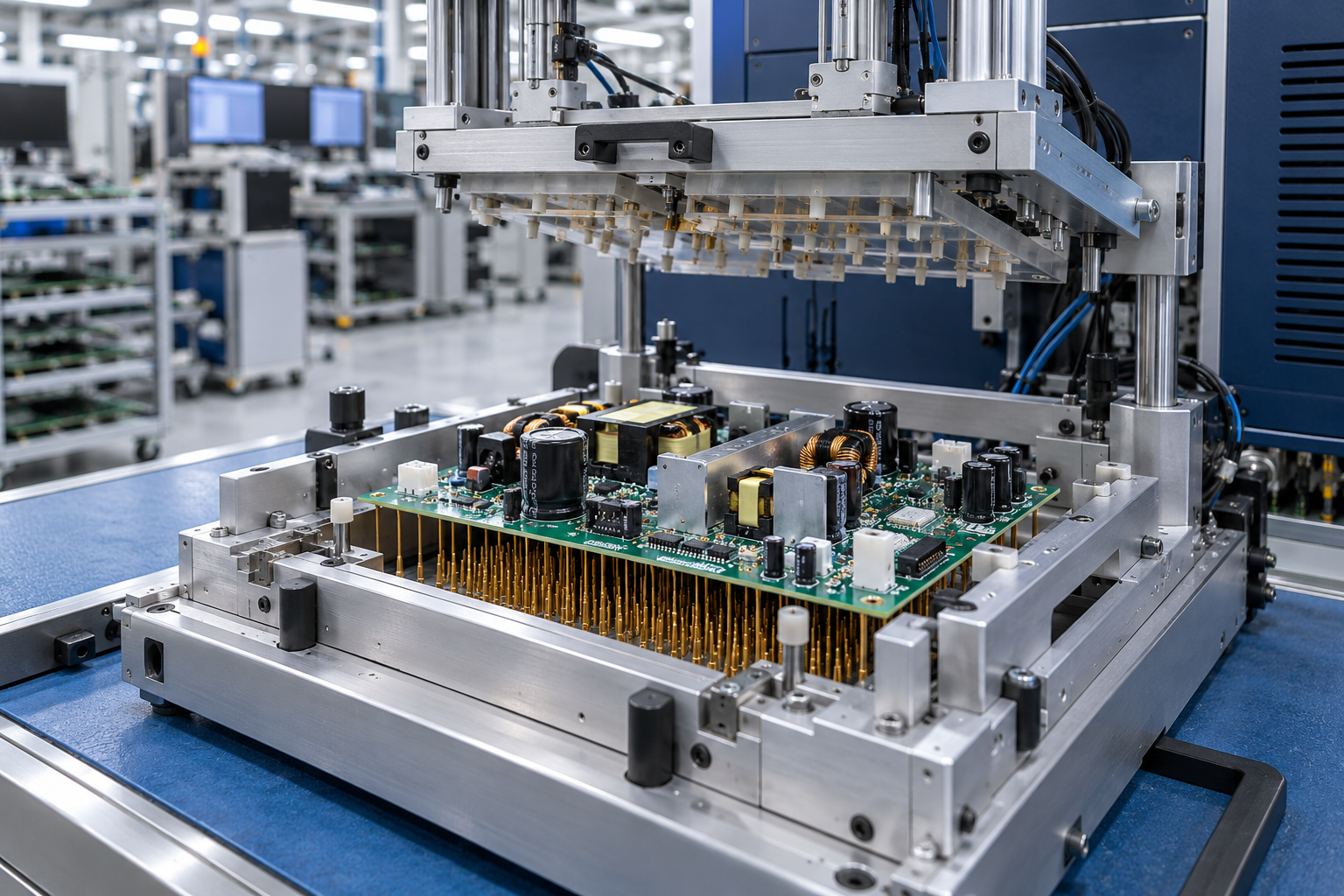
An in-circuit tester accesses specific nodes on a printed circuit board assembly through a bed-of-nails fixture or a flying-probe system. It isolates each component from the surrounding circuit using guard traces and measures its value, orientation, and connectivity independently. The test verifies that resistors are within tolerance and correctly valued, capacitors have the right capacitance and ESR and are not shorted, diodes and transistors are oriented correctly and not damaged, inductors are present and have the correct DC resistance, ICs are correctly placed with proper power and ground connections, solder joints are present and have acceptable resistance, and no solder bridges or opens exist between adjacent pins.
The key insight is that ICT measures the board at the component level, not at the system level. If a 10 kΩ resistor is populated where a 100 kΩ resistor should be, the ICT catches it even if the circuit still functions marginally. If a diode is installed backward, ICT finds it. If there’s an open via hidden under a component body that visual inspection would never spot, ICT catches it.
This level of coverage is why in-circuit testing is standard practice in automotive, medical, and high-reliability power supply manufacturing. The cost of missing a single defect in these applications — warranty claims, field service, liability — far exceeds the per-board cost of ICT.
How automated ICT integrates with functional test
In a typical production flow, ICT happens after soldering (wave or reflow) and before functional test. The board goes through the ICT station first. If it passes, it moves to functional test. If it fails, it gets routed to rework, and the data from the ICT identifies exactly which component or joint needs attention.
The reason ICT comes before functional test is simple: you don’t want to waste time functionally testing a board that has a fundamental assembly defect. A board with a solder bridge on the controller IC’s feedback pin won’t work in functional test anyway, but it might fail in a way that’s hard to diagnose. ICT tells you exactly where the problem is before you ever apply power.
Modern automated test equipment, including fully automatic PCBA ICT/FCT test systems, combines both test stages in a single automated workflow. The system picks up the board from the conveyor, performs the in-circuit test using a pneumatically actuated fixture, then transfers it to the functional test station for powered testing. In the Jettest ICT/FCT implementation, this dual-station design achieves throughput of 800 to 1,500 units per hour depending on board complexity.
One underappreciated benefit of combining ICT and FCT in one system is data correlation. When a board passes ICT but fails functional test, the combined data helps engineers understand whether the functional failure is caused by a component that ICT missed or by a design interaction that only appears under load. Over time, these correlations help refine both the ICT program and the functional test coverage.
Coverage versus access: the practical trade-off
The ideal ICT program tests every component on the board. In practice, access constraints limit coverage. Dense PCB designs, bottom-terminated components like QFN packages, and boards with components on both sides all reduce the number of nodes you can reach with a fixture.
For medium-volume production, flying-probe testers offer an alternative to bed-of-nails fixtures. They use two to four moving probes that contact each test point sequentially, eliminating the need for a custom fixture per board. The trade-off is slower test speed — flying probe is typically 5 to 10 times slower than fixture-based ICT. For low-volume, high-mix production, that’s acceptable. For high-volume lines running thousands of boards per day, fixture-based ICT is the standard.
Coverage targets vary by industry. For consumer power supplies, 80% to 90% component coverage is common. For automotive-grade power electronics, customers typically require 95% or higher. The remaining uncovered nodes are covered by functional test and visual quality inspection.
Design for testability (DFT) makes a significant difference in achievable coverage. Boards designed with test points on every critical net, at a spacing compatible with standard probe sizes, can achieve 98% or higher coverage. Boards designed without DFT consideration often struggle to reach 70%. The cost of adding test points during PCB design is negligible compared to the cost of diagnosing field failures on a board with poor test coverage.
The economics of in-circuit testing
Adding an ICT station to a production line costs money — the tester itself, the fixture, the programming labor. A typical fixture-based ICT system with a custom bed-of-nails fixture runs $30,000 to $80,000 for the hardware, plus programming time. So the question is always: does it pay back?
The math works because ICT finds defects early. A defect caught at ICT costs pennies to fix — a touch of solder, a component replacement, a quick retest. The same defect caught after final assembly might require disassembly, diagnosis, and retest, costing several dollars. If it escapes to the field, the cost can reach hundreds or thousands of dollars in warranty claims, shipping, and customer support.
For a production line running 100,000 boards per year with a 1% assembly defect rate, ICT prevents 1,000 defects from reaching functional test. At a typical cost ratio of 1:10:100 for finding a defect at ICT versus functional test versus the field, the savings quickly exceed the investment, often within the first six months on a typical production line.
There is also a throughput benefit that is harder to quantify but equally real. When ICT catches defects before functional test, the functional test stations spend their time on boards that are likely to pass. This increases the effective capacity of the test line without adding equipment. Boards that fail functional test because of a defect ICT should have caught represent wasted test time and reduced throughput.
The role of boundary scan and JTAG
For dense digital boards where physical access is limited, boundary scan (JTAG) testing supplements traditional ICT. By using the JTAG chain built into many modern ICs, boundary scan can test interconnections between chips without physical probe access. It’s particularly useful for checking opens and shorts on fine-pitch BGA devices.
In power supply manufacturing, boundary scan is most relevant on the digital control side — the microcontroller, the digital signal processor, and any communication interfaces. The power stage components still need conventional ICT coverage because they aren’t JTAG-compatible.
A combined strategy using ICT for analog and power components and boundary scan for digital interconnects provides the highest overall coverage. For power supply manufacturers producing boards with both a digital control section and a high-voltage power section, this dual approach is becoming standard practice.
Common ICT programming mistakes
Even with good hardware, an ICT program that is poorly written will miss defects or produce false failures. The most common mistake is setting test limits too tightly. Component tolerances stack up, and a resistor that measures 9.8 kΩ instead of 10 kΩ is still within specification, but a tight limit might flag it as a failure. The limit should be set to the component tolerance plus a margin for measurement variation.
ESR measurement on capacitors is another area where limits are often set incorrectly. A capacitor’s ESR varies with frequency and temperature. The same capacitor that measures 50 mΩ at 25°C might measure 80 mΩ at 60°C. If the test program uses a fixed limit without temperature compensation, good capacitors will fail on hot boards.
Guard placement matters for in-circuit measurement accuracy. A poorly placed guard can fail to isolate the component from parallel paths in the circuit, resulting in a measurement that reflects the component in parallel with other elements rather than the component alone. This typically requires iterative adjustment during test program development.
Quantifying the decision
In-circuit testing is the most cost-effective way to catch assembly defects before they become system failures. When integrated with functional testing in an automated line, it provides a complete picture of board quality at every production stage. For any power supply manufacturer producing at scale, the return on investment in ICT is a matter of when, not if. The combination of early defect detection, reduced rework cost, and improved test throughput makes it one of the highest-value investments a manufacturer can make in production quality.