
Communication Card JET-P5001A


Communication Card JET-P5001A
¥350.00
This is a multi-protocol communication conversion card that supports LIN/CAN to network communication. It integrates multiple mainstream industrial communication interfaces and allows network parameter modification via RS485, providing flexible and reliable data transmission solutions for industrial automation and intelligent control systems.
| Mechanical Dimensions(mm) | 114*84*17 |
|---|---|
| Delivery Time | To Be Negotiated |
Product Features
- Network communication: Supports LIN/CAN to network communication and network parameter modification via RS485.
- Power supply: 10~24V power supply, with a maximum current of 0.2A.
- Communication interfaces: 1-channel RS485, 2-channel CAN, 2-channel LIN, and 1-channel LAN.
Technical Specifications
| Parameter | Specification |
|---|---|
| Power Supply Parameters — Voltage | 12 V |
| Power Supply Parameters — Current | 0.15 A |
| 485 Parameters — Baud Rate | 115200 bps |
| 485 Parameters — Data Length | 8 bit |
| 485 Parameters — Stop Bit | 1 bit |
| 485 Parameters — Parity Bit | None |
| CAN Parameters — Arbitration Baud Rate | 50K-1M bps |
| CAN Parameters — Data Baud Rate | 100K-5M bps |
| CAN Parameters — CANFD | Supported |
| CAN Parameters — Terminal Resistance | 120 Ω |
| CAN Parameters — Extended Frame | Supported |
| LIN Parameters — Baud Rate | 2.4-20 Kbps |
| LIN Parameters — Sync Break Field | 10-14 bit |
| LIN Parameters — Checksum Mode | Classic and Enhanced Mode |
Dimensions
Length × Width × Height: 84 × 114 × 16 mm
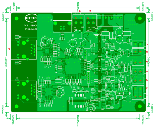
Port Definition and Pinout
| Port | Function and Pinout |
|---|---|
| P | Function: Ethernet Port Pin: Not specified in the source. Remarks: Connect to network cable |
| B | Function: Power Supply Pin 1、2: 12V power supply negative pole Pin 3、4: 12V power supply positive pole |
| C | Function: CAN2 Control Pin 1: CAN2-L data line Pin 2: CAN2-H data line |
| D | Function: CAN2 Control Pin 1: CAN2-L data line Pin 2: CAN2-H data line |
| E | Function: LIN1 Control Pin 1: GND Pin 2: LIN1-BUS data line |
| F | Function: CAN1 Control Pin 1: CAN1-L data line Pin 2: CAN1-H data line |
| G | Function: LIN2 Control Pin 1: GND Pin 2: LIN2-BUS data line |
| H | Function: RS485 Control Pin 1: RS485-A positive signal Pin 2: RS485-B negative signal |
| I | Function: RS485 Control Pin 1: RS485-A positive signal Pin 2: RS485-B negative signal |