APPLICATIONS / POWER SUPPLIES
Power Supply Load Testing and Burn-in Solutions
From multi-channel DC electronic loads to complete power supply burn-in systems, JETTEST provides equipment for server, telecom, industrial and adapter power supply applications.
Choose a load module for integration or a complete system for loading, temperature control and batch operation.
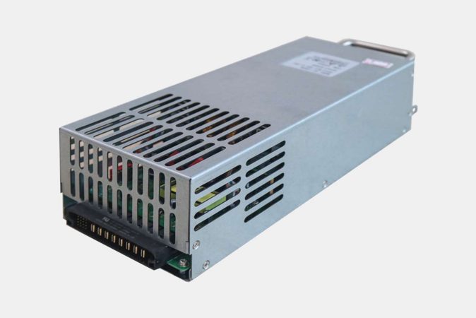
4-channel DC-DC load module · 400 W per channel
Power Supply Testing and Burn-in Challenges
A useful load and burn-in configuration must match the electrical operating points, the number of products running together and the required monitoring. A power rating alone is not enough to select equipment.
Electrical operating range
Provide minimum and maximum output voltage, maximum current, continuous power and the number of outputs. Include low-voltage operating points rather than only the PSU nameplate power.
Load control & communication
Define CC, CV, CP or CR requirements and the host communication interface. Keep load-module control separate from DUT communication such as PMBus/IIC.
Thermal & energy configuration
Define temperature, duration and simultaneous units. Check the DC bus or AC backend arrangement and the system’s energy-recovery configuration.
Ripple, efficiency, transient-response and electrical-safety measurements require suitable instruments and test procedures. They are not implied by the presence of an electronic load.
Power Supply Applications and Test Requirements
Server & Telecom PSUs
Match output ratings and channel count to the required load configuration. For burn-in, define the number of connected units, operating temperature and test duration.
Industrial & LED Power Supplies
Evaluate multi-channel DC load modules against each output’s voltage, current and power requirements. Select the control mode needed for the test.
Chargers & Adapters
Plan batch burn-in around per-unit power, connection fixtures and simultaneous test positions. A dedicated charger configuration provides 120 positions at 180 W per position.
Choose a Module or a Complete System
| Option | When to consider it | What to confirm |
|---|---|---|
| Electronic load module | Adding electrical loading to a test platform. | Control, connections, cooling and backend energy path. |
| Power supply burn-in system | Combining loading with temperature control and batch operation. | Per-position rating, product count, duration and monitoring. |
| Regenerative burn-in system | A burn-in project requiring an energy-recovery configuration. | System topology, compatible backend and site electrical conditions. |
DC Electronic Load and Bidirectional Power Modules
Choose the module around the number of outputs, per-channel power and required operating range. These modules are components for integration into a suitable load or burn-in configuration.
4-channel DC-DC Electronic Load
4 channels · 400 W per channel
For loading server, industrial, adapter and LED power supplies. Review each output’s operating points and the required backend energy path.
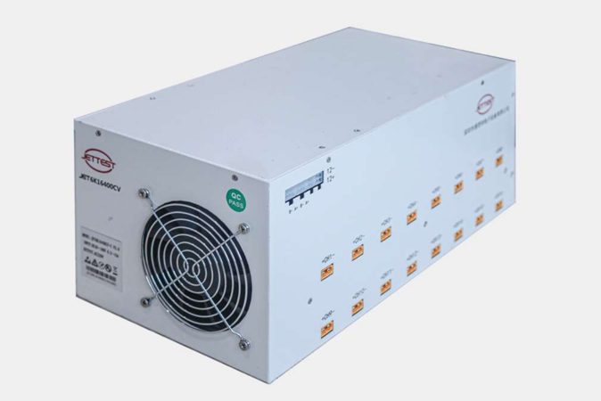
16-channel DC-DC Electronic Load
16 channels · 300 W per channel
For projects requiring multiple DC loading channels. Match each channel to the product output and confirm wiring, cooling and control requirements.
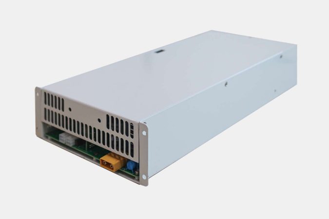
Bidirectional DC-DC Power Module
1 channel · 7.5 kW input power
For higher-power loading configurations. Check the selected voltage/current variant, conversion topology and compatible backend.
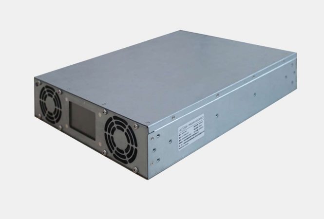
Dual-channel Bidirectional DC-DC Module
2 channels · 10 kW input power per channel
For projects requiring two higher-power channels. Confirm each channel’s operating envelope and RS485/CAN integration requirements.
Compare Load Module Specifications
| Module | Channels | Input power per channel | Modes and interface |
|---|---|---|---|
| DC-DC load | 4 | 400 W | CC/CV/CP/CR; RS485 |
| DC-DC load | 16 | 300 W | CC/CV/CP/CR; RS485 |
| Bidirectional DC-DC | 1 | 7.5 kW | CC/CV/CP/CR; RS485/CAN |
| Bidirectional DC-DC | 2 | 10 kW | CC/CV/CP/CR; RS485/CAN |
Compare channel-level ratings and interfaces first. Voltage and current ranges vary by configuration; maximum voltage, current and power are not interchangeable operating points.
CC: constant current · CV: constant voltage · CP: constant power · CR: constant resistance. DC-DC load modules require a compatible backend energy path; a DC output rating alone does not establish a standalone grid-regenerative system.
Complete Power Supply Burn-in Systems
Select a complete system when the project requires loading together with product connections, controlled temperature and batch operation.

Server PSU Burn-in System
40 positions · 2,400 W per position
CC/CV loading; product-zone temperature from ambient +10°C to 60°C. Confirm the customizable ATX output connector against your PSU pinout.

Telecom PSU Burn-in System
48 positions · 800 W per position
CC/CV loading; product-zone temperature from ambient +10°C to 60°C. Review the input supply, connectors and required operating conditions.

72 kW Regenerative Burn-in System
72 kW total regenerative load rating
Temperature range from ambient +10°C to 70°C, loading-current control, data acquisition and PMBus/IIC communication. Product capacity depends on power band and A/B configuration.
Compare Burn-in Configurations
| System | Product positions | Power rating |
|---|---|---|
| Server PSU | 40 | 2,400 W per position |
| Telecom PSU | 48 | 800 W per position |
| Chargers and adapters | 120 | 180 W per position |
| 72 kW regenerative system | Depends on power band and A/B configuration | 72 kW total regenerative load rating |
Module channels and system product positions are different measures. Neither specifies hourly throughput. Confirm the selected voltage/current variant and operating envelope before choosing a configuration.
Also Available: Charger and Adapter Burn-in
For lower-power charger and adapter batches, JETTEST offers a dedicated configuration with 120 positions at 180 W per position. Select it around product connections and required loading conditions.
Load and Burn-in Configuration Workflow
01 · Define the DUT
Voltage, current, power, outputs and connections.
02 · Select the load
Modes, channels, interfaces and electrical limits.
03 · Set burn-in conditions
Temperature, duration, unit count and monitoring.
04 · Review integration
Fixtures, controls, backend and site requirements.
Define Your Equipment Configuration
Load modules and complete systems
JETTEST offers multi-channel DC loads, bidirectional power modules and dedicated power supply burn-in equipment. Compare component-level integration with complete equipment configurations.
Defined server PSU configurations
A dedicated server PSU system provides a concrete starting point for reviewing product count, per-position power, load modes and connections.
System control and communication
Review loading-current control, data acquisition, PMBus/IIC communication and PS-ON control against your product and process requirements.
Related Application: AI Power Supply Assembly and Testing
JETTEST offers an assembly and test line for 3 kW and 5 kW AI power supplies, including burn-in and ATE stages. Load selection depends on the electrical specifications and test requirements of the power supply.
Power Supply Testing Questions
Should I choose a load module or a complete burn-in system?
A load module provides the specified electrical loading functions. A complete burn-in system combines loading with the published temperature, connection, monitoring and control configuration. Select according to the equipment you already have and the functions your project requires.
Can one module operate at maximum voltage and maximum current simultaneously?
Do not assume so. Confirm the selected variant’s voltage/current ranges, power limit and operating envelope. The maximum figures in different range options should not be combined into a single operating point.
Does a bidirectional module automatically provide a complete regenerative system?
No. Confirm its conversion topology, interfaces, energy path and compatible backend. Module conversion efficiency should not be presented as the electricity savings of an entire burn-in installation.
How do you test a power supply with an electronic load?
When testing a PSU, define output ratings and acceptance limits, select a compatible DC electronic load, and specify the required operating points. Record the required results using suitable instruments. Burn-in adds a defined duration and, where specified, controlled temperature.
How should a burn-in chamber be specified?
Specify product count, per-unit load, connections, temperature and duration. A burn-in test chamber must be evaluated with its load and control configuration. High temperature testing is limited to the selected equipment range; it does not automatically include thermal cycling or environmental stress screening.
Discuss Your Power Supply Load and Burn-in Requirements
Share your power supply specifications, simultaneous test quantity, temperature and duration, communication requirements and connector details to discuss a suitable equipment configuration.