
1. Introduction
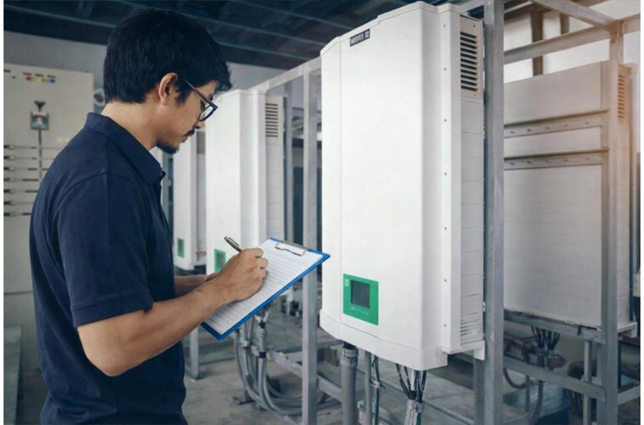
Modern inverters are a core part of several important electronics around us, both in the household & utility sectors. You will find them in uninterruptible power supply systems and variable frequency drives, from automotive electronics to aerospace and military systems. Manufacturers allocate huge resources for inverter testing so that they can meet the promise that starts long before commissioning and installation.
These testing routines are quite complex as well; a typical workflow may include testing processes to rate inverters’ units’ performance. Moreover, manufacturers maintain safety and durability through a structured sequence of automated checks, which typically include functional testing, checks for efficiency, extended burn-in/aging cycles, & communication verifications.
The real-world results of these inverter quality testing schemes are as good as the testing infrastructure itself. With the AI revolution in place, manufacturers are now moving to modern automated testing routines with advanced testing equipment for producing inverters, battery packs, and modern energy equipment at scale. In this article, we explore this industry from the perspective of manufacturers and what’s changing in this niche.
2. Evolving Inverter Testing in 2026?
No matter the inverter for solar or energy storage systems, modern electronics for power systems have made this product category astronomically complex. Inverters of 2026 are designed to handle bidirectional power flow for battery storage integration and support hybrid configurations (solar, storage, and backup power) and can also communicate continuously with BMS & related monitoring platforms.
This complexity level demands testing equipment that is equally smart to catch anomalies in complex inverter circuits. Modern testing equipment can now validate multi-protocol communication in an inverter’s channels, simulate real-world load, simulate charge/discharge cycles, and spot subtle performance deviations across a wider range of inverter operating conditions in different applications.
This complexity isn’t limited to solar and storage industries as other manufacturing like EV industry now use advanced automotive electronics testing protocols that has converged on many of the same challenges. This is because of onboard inverters & DC-DC converters in EVs face similarly demanding multi-protocol communication and load-cycling requirements
In 2026, understanding and investing in modern testing equipment is a baseline expectation, as it has also become extremely important for manufacturers to be a competitive differentiator and stay relevant in the current Industry 4.0/5.0 landscape.
3. Core Equipment for Inverter Testing Lines
3.1 Automated PACK Assembly & Final ATP Lines
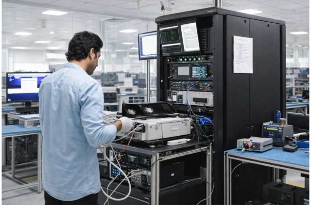
Modern infrastructure uses “automated” PACK assembly lines, which are designed to integrate mechanical assembly with inline testing stations working at several checkpoints. All this happens within the production process, not as another separate test phase.
Whereas the final acceptance test procedure, or ATP, is usually performed at the end of battery pack manufacturing lines alongside inverters. Consider this as a final quality check before the produce inverter is finally readied to be shipped. This is the last comprehensive check and is usually done with a well-documented procedure that includes tests such as functional verification of the inverter, all relevant safety checks, & traceability confirmation.
3.2 Burn-In/Aging Systems
Inverters are exposed to controlled load & thermal stress for extended periods to record their response to detect errors related to marginal components in the produced batch and workmanship defects. The testing equipment designed for this layer of testing is capable of running large batches of inverters (or battery packs) simultaneously and runs with automated monitoring systems.
For ordinary inverter systems headed to commercial markets, the aging time is typically 24 to 72 hours to test all the required functions. But the time frame and rigor of these tests depend on the manufacturer’s risk tolerance and the product category itself. For example, inverters made for utility-scale or safety-critical applications are exposed to weeks of aging tests.
3.3 Automated Test Equipment
Companies usually opt for ATE when scale is required without any compromises in quality. These stations are designed to automatically apply simulated input conditions for inverters to check their normal operations. Manufacturers use them to accurately validate power conversion accuracy in the inverter circuitry, monitor and improve efficiency curves, and validate all the included protection functions & communication protocols.
Moreover, they also get to compare the output test data of each shift, production batches, and, in some cases, products from different factory locations. All of this can be done due to a consistent and automated sequence of ATEs.
3.4 Environmental Test Chambers
Inverters are usually outdoor devices and can easily be exposed to external surroundings where the temperature rises and drops every day, along with dust, humidity, wind, and other external forces. This is common for inverters used in utility-scale or off-grid deployments where they experience extreme natural conditions.
These testing chambers are designed to simulate all of these conditions and help manufacturers get a realistic picture of how a unit from their batch will actually perform once installed. In these conditions, there won’t be any “quick help” for the customers to fix their inverters if there is an induced fault from the environment; this is also taken into consideration.
4. Core Inverter Quality Testing Protocols
4.1 Insulation Resistance
As mentioned above, inverters are usually exposed to external forces, and any compromise in integrity and insulation can lead to major issues, especially when outdoors. Any unintended leakage to the chassis or ground can easily lead to current loss or lead current outside of the conductive paths.
For this, ATE systems apply a controlled test voltage across the conductors in the inverter and its ground. This automatic process measures electrical resistance against a defined minimum threshold (for the leakage current in the event of an anomaly) before an inverter is cleared for subsequent tests.
4.2 Power Quality Testing
The above-mentioned, as crucial as it seems, is still considered a basic level test; once verified, the next protocol is related to the power quality being delivered by the inverter itself. For this, harmonic distortion testing is used, which is done to measure how much an inverter’s output, if faulty, deviates from a pure sine wave as it should be according to the design specifications.
Again, automated test systems are used for this stage, which can monitor the output and capture the full output waveform. This is done in varying load conditions, and the systems automatically capture total harmonic distortion (or THD) in the power output, flagging any unit whose output falls outside acceptable limits.
4.3 Grid Support Function Testing
One of the areas where inverter technology has really stepped up in different applications is its ability to not just convert power but also add stability to the attached grid. Modern inverters are designed with low & high-voltage ride-through, frequency response, and reactive power support.
To check whether an inverter performs in terms of grid stability, manufacturers simulate required grid conditions directly on the test line rather than making them a separate test phase. During this, inverters are exposed to external pinches like uncontrolled voltage sags, surges, and frequency deviations. The response in grid support is checked, and results are documented against related compliances.
4.4 Component Stress Testing
All the previous testing schemes are designed to check the response as a whole, but this latter targets power electronics, capacitors, cooling systems, etc., all the “components” of the inverter itself. Sometimes, overlapped with burn-in in the testing layer, this one is more of a targeted testing process.
This testing scheme is done on a sampling basis, especially when manufacturers are testing a new design or a revision is introduced in their previous models. Common component stress tests use techniques like overheating, stressing capacitors, and cycling rapid load changes to test the transient response of the inverter’s output circuit.
4.5 Communication/Integration Checks
Modern inverter technology is powered with AI systems & runs in an interconnected ecosystem by communicating with BMS platforms and site-level controllers. Manufacturers use advanced testing systems that validate these communication channels of the inverter under realistic conditions. The parameters checked usually include status, maintaining stable communication under stressed/normal conditions & also accepting remote commands.
5. Key Performance Indicators to Track
5.1 Efficiency and Conversion Ratios
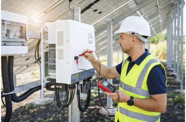
ATE systems are usd to monitor this KPI across the full rated range of load conditions rather than at a single operating point during which it checks the he ratio of usable AC output to DC input. If there is tightening, or even a gradual drift in the efficiency curve generated from ATEs test data, it means that there are issues in components that can’t keep up at different loads.
5.2 Availability and Uptime
Linked with burn-in and aging data from the above-mentioned testing schemes, this KPI is an ultimate metric for manufacturers. This number is the most common predictor to uphold warranty claims, and the burn-in/aging tests help them verify it, during which manufacturers check the failure rate of a unit or how much drifting it shows from the default spec during extended stress cycles.
5.3 Response Time to Grid Events
Inverters can pack advanced features from multiple channels to support rigorous layers of security, but how fast they do all of that counts. This KPI is usually measured during grid support function testing (as discussed above) on the ATE. Engineers compare the actual response time of the manufactured unit against the specification from the manufacturer.
5.4 Degradation Trends Over Time
Again linked to advanced and much more rigorous aging cycles, this KPI is linked with inverters’ efficiency, thermal performance & output stability. Since such problems only show after years of use, manufacturers now use automated and AI-powered equipment to simulate external degradation forces and compare their data across different production batches, inventors’ component suppliers, or design revisions.
6. Complete Ecosystem for Inverter Testing
One of the most common on-field troubles for inverter manufacturers is the incompatibility issues between different equipment used for testing routines mentioned above. PACK assembly stations, burn-in equipment, environmental chambers & ATE systems from separate vendors are one of the most common issues reported in 2026 for inverter manufacturers in different industries.
Jettest solves this problem with its state-of-the-art and industry-redefined full testing and automation product ecosystem. It covers all the inverter testing requirements and KPI hustle we discussed above. The most noticeable and high-demand is the Photovoltaic power supply test system designed to verify the reliability of inverter systems to the utmost standards.
It works by simulating 0 to 1500V DC input and AC load conditions, an industry-standard 150 kW number for burn-in/test product power, and comes with extreme MES protocol compatibility and whole-line data traceability. It can be used for different applications, including PV, modern energy storage, and standalone inverter products.
7. Wrapping Up
Proactively catching & preventing production quality issues in modern inverters helps companies stay competitive and extends the lifetime of their products. Modern inverter testing systems to prevent quality issues are much smarter, faster, and interconnected, and they perform at the factory & production line.