
There is a question every production test engineer hears eventually, usually from a customer services manager holding a batch of returns: “How did these units pass the factory test?” The answer is often buried in a measurement that was performed but never really understood. For power supplies, that measurement is line regulation, and more times than I can count, a marginal design has slipped through because line regulation was tested once at nominal input and never again.
Line regulation answers a simple question: how much does the output voltage change when the input voltage changes? It sounds straightforward. Measuring it well is another story, and testing it properly in production catches failures that efficiency and load regulation checks simply miss.
What line regulation actually measures
Line regulation is the ratio of output voltage change to input voltage change, usually expressed as a percentage of the nominal output. If a 12 V supply is specified with line regulation of 0.5%, a change in input from 100 VAC to 240 VAC should move the output less than 60 mV. The data sheet number is a promise about how well the control loop rejects input disturbances.
There are two common ways to state it. Most manufacturers use the percentage-of-nominal-output form: (Vout_max − Vout_min) / Vout_nominal × 100%. Some automotive and industrial specs use absolute millivolts instead. Either way, the measurement only means something if the input is actually varied across its rated range while the load stays fixed. A common mistake in rushed test plans is sweeping the input with a load that drifts, which produces a number that mixes line and load effects and cannot be compared against the spec.
The control loop is the star of this show. A well-compensated feedback loop holds the output steady as the input moves. A loop with too little gain lets the output follow the input ramp. The interesting failures come from the parts between the loop and the test points: reference voltage drift, optocoupler current transfer ratio change with temperature, and transformer winding ratios that shift with core saturation.
Why production testing matters more than the lab
A design engineer validates line regulation once, over a few units, on a bench with a clean AC source and controlled temperature. Production sees a different world. Component tolerances spread across every unit. A batch of optocouplers with a slightly low current transfer ratio can push output regulation to the edge of the spec even though every individual component passed its own inspection.
This is why line regulation is not a design-only test. It is a production test. The units that fail line regulation in manufacturing tend to fail in a characteristic way: marginal components combined with input voltage at the extremes of the range. These are exactly the units that pass a nominal-input functional test and come back from the field with “output out of spec at high line” complaints.
There are three drift mechanisms worth knowing about, because they show up in production data before they show up in the field:
Reference voltage drift is the first: the internal reference is usually a bandgap or zener-based circuit, and if it drifts with temperature, line regulation looks fine at 25 °C and degrades at the hot end of the burn-in chamber. Optocoupler CTR aging comes next — over life, the current transfer ratio falls, so units near the edge of the CTR spec pass at first production and fail after thousands of hours. Transformer saturation at high line is the third: at the top of the input range, core saturation can cause output deviation that only appears at full load.
Each of these shows up as a line regulation failure only if the production test actually exercises the input voltage range. Test plans that check line regulation at nominal input only are, for practical purposes, not testing line regulation.
How to measure it without fooling yourself
The measurement setup sounds trivial: vary the AC input, read the DC output, compute the ratio. The traps are in the details, and they are the reason two labs can measure the same supply and get different pass rates.
First, the AC source must be stable and repeatable. A wall outlet is not a test instrument. The mains in most factories wanders several volts, and a test that “varies the input from 100 V to 240 V” using the wall will produce garbage. A programmable AC source with a regulated output and a defined impedance is the minimum. Watch the source’s settling time: the output of the supply under test can ring when the input steps, and if you sample during the ring, you log a transient that is not line regulation.
Second, use a true RMS voltmeter or a calibrated power analyzer for the input measurement. The output side needs a high-resolution DC measurement, ideally four-terminal, because the current drawn by the load generates a voltage drop across the test leads. For low-voltage outputs, a 50 mV drop on a 5 V rail is a percent of error in the regulation measurement, which can flip a passing unit to failing and back.
Third, decide on the load behavior. Line regulation must be measured at a fixed load. The clever trap is a load that is set under program control and settles slowly; if the load has not settled before the input step, the measurement captures a mix of line and load regulation. Sequence the test so the load is stable for several hundred milliseconds before the input changes.
Fourth, choose the measurement points deliberately. The standard benchmark set is low line, nominal, and high line, at light load, half load, and full load. That is nine points minimum, and each one should be measured after the output has settled. Rushing the settle time is the most common way to produce optimistic numbers.
What the spec sheet is really telling you
Reading a line regulation spec critically saves a lot of confusion. A headline number like 0.5% usually applies at 25 °C, at one load point, and over the full input range. The fine print matters:
Some vendors spec line regulation at fixed output current but define it as a percentage of the measured output rather than the nominal output, which makes the number look better than it is. Temperature coefficient is a separate spec but interacts with line regulation, which is why hot-room testing at high line is the combination that catches failures. Cross-regulation on multi-output supplies is usually worse than the main-output spec, because the auxiliary rails get less loop gain and show more input sensitivity.
When you plan a production line regulation test, your limits should come from the data sheet applied to your production temperature range, not from a fixed 0.5% that someone picked because it sounded reasonable.
Where line regulation testing belongs in the manufacturing flow
Line regulation fits naturally into the functional test station, usually in the same program segment as load regulation and efficiency, because all three use the same electronic load and AC source. Running them together eliminates a second handling step and keeps the measurement conditions consistent.
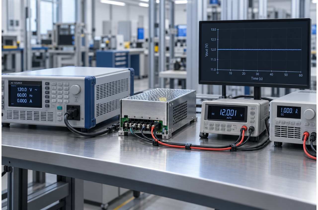
On automated lines, this is where automated testing solutions pay for themselves. A scripted sequence steps the AC source through the input range, waits out the settle time, reads the DMM, checks against the per-point limits, and logs pass or fail with the raw measurements. The operator watches the summary, not the scope. The same station can fold in dynamic tests, like a load transient while the input is at low line, which is the true worst case for regulation.
The data from that station is more valuable than the pass/fail bit. Plot line regulation against serial number or against manufacturing date and you get early warning of a component lot shift. Regulation numbers trending toward the limit are the signature of a supplier change or a process drift; the production data tells you about it weeks before field failures do.
When marginal units make it out the door
Let me close with the scenario that prompted this article. A customer’s power supply had passed every production test for three years. Then a new batch of transformer cores arrived, and field returns started climbing. The units passed nominal-input tests at the factory. The customer’s equipment supplied 90 VAC at extreme sites and the returns all came from those locations. A line regulation check at the bottom of the input range, added to the production test, flagged the bad batch within a week of the core change. The trend chart identified the date, and the traceability system identified the incoming lot.
That story has one lesson: nominal-input testing is comfortable, but the edge of the input range is where the failures live. The test equipment matters too. Power testing equipment with programmable AC sources, accurate DMMs, and stable electronic loads gives the test engineer the settling time and repeatability that the measurement demands.
The habits that keep line regulation honest
A few habits separate teams that get reliable regulation data from teams that get numbers they cannot trust. Record the input source model and the settle time in the test procedure. Calibrate the DMM and the AC source on a fixed schedule. Measure low line and high line on the same station with the same cabling. And review the regulation trend, not just the pass/fail rate, at least monthly.
Line regulation is not the hardest test on a power supply test plan, but it is one of the most revealing. It exercises the control loop, the reference, and the magnetic components all at once, and it does it at the input conditions where real installs actually operate. For a manufacturer of burn in test systems and automated test equipment, line regulation is a standard segment of the functional station Jettest builds for server power, telecom rectifiers, and industrial supplies. Their test programs typically execute the nine-point line regulation matrix with the settle time locked in, so the data is comparable across shifts and across years.
If your production reports have a line regulation segment that nobody looks at, that is a wasted measurement. Give it the right points, the right settle time, and a trend chart, and it will start paying you back with the first batch of marginal units it catches before they ship.