
Every field return has a story, and the one that stuck with me started with a warehouse pallet of power bricks. The customer had run a full functional test at the factory. Line regulation, load regulation, efficiency spot checks, all green. Six weeks later, half a batch of units came back with blown input fuses and one burned bridge rectifier. The lab found the cause in about an hour: a soft-start circuit that worked fine when the production tester pre-charged the bus slowly, then let the first cold plug-in spike run uncontrolled on the customer’s bench.
That failure mode is exactly why inrush current, and especially cold-start inrush current, should be measured as its own step rather than folded into a generic power-up pass.
What [[inrush current]] is, in plain terms
When a power supply connects to the mains, the input capacitors are empty and the converter needs to charge them almost instantly. The input circuit sees a current surge far above the steady-state value for a few milliseconds. On a 240 VAC line, a modest 250 W supply without a soft-start limiter can pull tens of amperes at the moment of connection. The physics is not complicated, but the measurement is easy to get wrong.
This surge is not a defect by itself. Every switch-mode supply has one. The design question is whether the limiter keeps the peak inside what the fuse, rectifier, and EMI components can survive, including across thousands of connect/disconnect cycles.
Why the drawing never tells the whole story
Schematic simulations of inrush current look clean. The simulator runs, the peak lands inside the expected window, and the design review moves on. But a simulation uses ideal component models, a fixed line impedance, and one temperature point. Real production parts vary. An NTC thermistor that reads 10 ohms at 25 °C reads differently at 0 °C, and a supply that passes the inrush check on the bench in summer can show a higher peak when the same model ships to a customer in a colder climate. That is why the measurement belongs on the test floor, not just in the design tool.
Line impedance is another variable that hides in the drawing. A stiff, low-impedance AC source in the lab feeds current more readily, so the inrush peak measured on the bench can be higher than what a customer with a long, thin extension cord experiences. That sounds like a safety margin in your favor, but the reverse happens too: a weak line that sags under load can starve the soft-start circuit and change the charging profile. The practical approach is to document the source impedance used during characterization and keep it consistent for production testing.
What the standards actually ask for
Inrush current shows up in several product safety and performance standards, and knowing which clause applies helps you design the right test. IEC 62368-1, used for audio/video and IT equipment, limits the inrush current delivered to the mains at switch-on. IEC 61000-4-11 covers voltage dips and interruptions and, while it is about immunity rather than inrush, it makes you think about what the supply does when AC comes back after a partial loss. For industrial equipment, IEC 61000-4-34 addresses voltage dips for equipment with input current above 16 A per phase, where a large inrush on one unit can drag down the whole installation.
None of these standards tell you exactly how to run an inrush measurement on your production line. They define limits and test conditions, and it is up to your test engineering team to build a station that repeats those conditions unit after unit. That is where a fixed phase-angle switch and a saved waveform mask earn their keep: they remove the operator judgment from a measurement that is easy to get wrong.
A quick reference table for the test setup
| Parameter | Typical setting | Why it matters |
| Scope trigger | Rising edge on voltage, single shot | Catches the first peak, not a steady-state frame |
| Sample rate | ≥ 2.5 MS/s | Resolves a peak that rises in tens of microseconds |
| Current sensing | Clamp probe or low-inductance shunt | Preserves the transient shape |
| Cool-down time | 3–5 minutes between cold starts | Ensures capacitors discharge fully |
| Input voltage | Min, nominal, max | Peak scales with line voltage |
| Phase angle | Record which angle produced max | Repeatability across production runs |
The table above is a starting point, not a substitute for your own characterization. Every topology behaves a little differently, and the values should be set from data, not from a template.
Cold start versus hot start: two different events
A cold start means the input capacitors start from zero charge, usually several minutes after the supply was last powered off. A hot start means the unit was running recently and the caps still hold most of their charge when you re-apply power.
They are genuinely different tests, and treating them as interchangeable is the first mistake I see in test plans:
A cold start produces the maximum possible peak because the capacitors present a near short circuit to the line at the moment of connection, which makes it the worst-case stress for the fuse and rectifier. A hot start produces a smaller inrush because the residual charge softens the initial current demand; it is still worth measuring, but it will not tell you whether the fuse is oversized or the NTC is doing its job.
The production tester should therefore record both, with a defined cool-down interval between power cycles so the cold-start reading is actually cold. If your test spec says “power cycle with 1 second off,” your cold-start data will quietly become hot-start data and the worst case disappears from the report.
How to capture the real peak
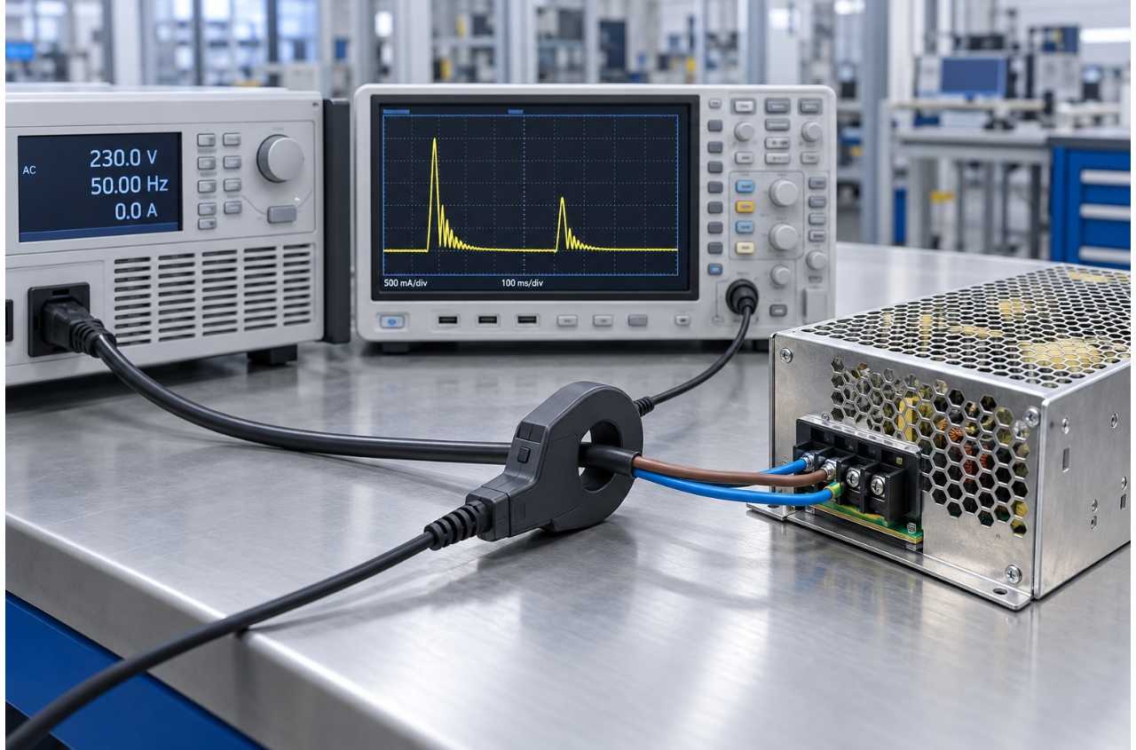
Measuring inrush with the wrong instrument is a classic way to get confident, wrong numbers. A multimeter in current mode cannot see a few-millisecond transient. The reliable setup is a digital oscilloscope with a current probe, or a low-inductance shunt, triggered on the rising edge of the line voltage.
A few practical points from the test bench:
Set the sample rate high enough for the transient, because a 2.5 MS/s rate on a standard scope will miss a narrow first peak that rises in dozens of microseconds. Use single-shot triggering and let the scope capture the first half cycle, which is where the highest peak lives. Add a defined connect angle, since the peak shifts with where in the AC cycle the power is applied, and that is exactly why certification bodies test at the phase angle that produces maximum inrush. Record both the peak current and the time-to-steady-state, because the duration matters as much as the peak for fuse selection.
One detail that surprises people: the biggest cold-start inrush often appears in the second or third half cycle, not the first, when the PFC inductor joins the charging path. If the scope window is too short, the true maximum never lands in the capture.
What to check after the measurement
A good inrush test does not stop at recording a number. The checklist that catches real problems includes:
Compare the measured peak to the fuse minimum melting characteristic rather than just to the fuse rating, because a fuse rated for 3 A can still open if the I2t of the surge exceeds its let-through. Verify that the soft-start path actually engages; an NTC shunted by a relay that never closes will show correct inrush but a hot unit that runs hot in steady state. Repeat the test at the rated minimum and maximum input voltage, since many designs get characterized at nominal line only and the inrush at 264 VAC can be meaningfully higher. And check what happens on rapid brown-out recovery, because a supply that reconnects while the PFC stage is mid-discharge can produce an unusual pulse.
Where this fits in production and burn-in
In production, the inrush check belongs in the same station family as the rest of the electrical safety and power-on tests, sequenced before load testing so the unit enters the load stage known good. For higher-volume lines, this is where automated testing solutions earn their keep: a proper fixture sequences the mains phase angle, captures the waveform, compares it to a saved golden mask, and logs the result without waiting for an operator to interpret a scope screen.
The other place inrush matters is at the start of a burn-in cycle. Every unit passing through burn in testing connects under the same cold capacitor conditions, and if the limiter degrades over the product’s life, the burn-in station is often the first place the trend shows up. That is a free early-warning signal many factories ignore until a field failure forces the question.
When you should treat inrush seriously
Not every product needs a dedicated inrush characterization effort. The risk scales with input power, with the number of units on a shared line, and with how often the end user cycles power. A 5 W wall adapter on a dedicated outlet is low risk. A rack of server supplies, or a charger for an industrial tool on a crowded circuit, is a different story: the aggregate surge of several units connecting at once can trip building protection even when each unit passes its own test.
The engineering habit that prevents most of these problems is small: measure cold start and hot start separately, keep the measurement method documented, and make sure the production station exercises the unit the same way the end user will. That last sentence sounds obvious, and it is exactly the step that was missing in the story that opened this article.
Jettest, a Shenzhen-based manufacturer of power supply burn-in and automated test systems, has spent the past eighteen years integrating inrush current testing into turnkey test and aging lines for consumer electronics, server power, and electric vehicle onboard chargers. Their engineers typically place the inrush capture in the first power-on station, before aging, so every unit’s cold-start behavior enters the manufacturing data trail. If you are setting up a new production test sequence or trying to understand why returned units show fuse failures that factory testing never caught, walking a cold-start measurement into the test plan is a cheap fix with an outsized payoff.