
The leakage current limit on a hipot tester is just a number in the test program. Too low, and every unit on the line fails. Too high, and insulation defects that should be caught slip through. Getting it right requires understanding where the current actually comes from during a dielectric withstand test and how to distinguish between capacitive charging, normal leakage, and genuine breakdown.
The leakage current that a hipot tester measures is the sum of several components: the capacitive charging current (especially in AC testing), the insulation resistance leakage, the surface leakage across the insulation, and, in the case of a failure, the breakdown current. Only the last one indicates a problem. The first three are always present to some degree, and their magnitude depends on the product’s design, the test voltage, and the environment.
What contributes to measured leakage current
In an AC hipot test on a switching power supply, the largest component of the measured current is usually capacitive. Y-capacitors between the primary circuit and ground, which are required for EMI compliance, present a low impedance path at 50 or 60 Hz. A 4.7 nF Y-capacitor at 1,500 VAC and 60 Hz draws about 2.7 mA of current. Two such capacitors in parallel draw about 5.4 mA. That’s just the Y-capacitors — before any insulation leakage is measured.
The insulation itself contributes a smaller current. The impedance between primary and secondary windings in a transformer, the creepage distance across the PCB, and the insulating barriers in optocouplers all have finite resistance. This component is typically in the microamp range for good insulation and doesn’t affect the pass/fail decision unless the insulation is compromised.
Surface leakage varies with humidity and contamination. A board that has flux residue from wave soldering will show higher leakage current during hipot testing, especially in humid conditions. This is why hipot testing is ideally done in a controlled environment and why test fixtures need regular cleaning.
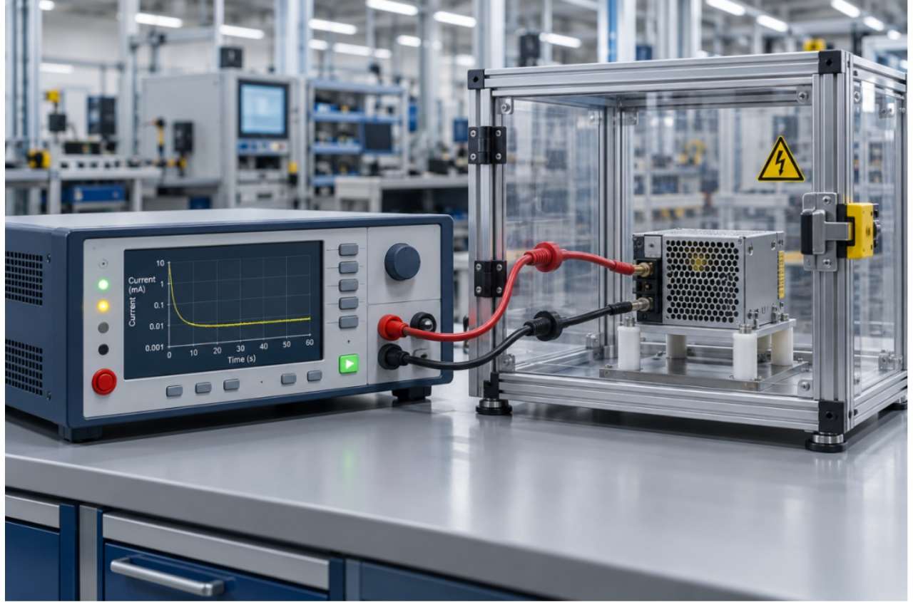
For DC hipot testing, the picture is different. The Y-capacitors charge up during the voltage ramp and then draw negligible current once charged. After the initial charging transient (which typically lasts 0.5 to 2 seconds depending on the capacitance and the tester’s current capability), the measured current drops to the insulation leakage and surface leakage components only. This is the main reason DC hipot testing gives a cleaner, more repeatable measurement for power supplies with Y-capacitors.
Another component worth understanding is the dielectric absorption current. When DC voltage is applied to insulation, the dielectric material gradually polarizes, drawing a current that decays over seconds to minutes. This is not a leakage current in the traditional sense — it’s a charging phenomenon within the insulation material itself. In DC hipot testing, the absorption current adds to the initial charging transient and can take 10 to 30 seconds to decay fully. Test programs that evaluate leakage too early after voltage application may see elevated current that is not indicative of insulation failure.
Setting the limit for production testing
For AC hipot testing of power supplies, the leakage current limit is typically set between 5 mA and 20 mA, depending on the product’s Y-capacitor configuration and the safety standard’s requirements. A common production limit is 5 mA for AC testing at 1,500 VAC. For products with multiple Y-capacitors or higher capacitance values, the limit may be set at 10 mA or higher.
The challenge is that 5 mA is often close to or below the capacitive current contributed by the Y-capacitors alone. If a product has three Y-capacitors totaling 10 nF, the capacitive current at 1,500 VAC and 60 Hz is about 5.6 mA. Any unit with this configuration will exceed a 5 mA limit even with perfect insulation. This is where DC hipot testing has a clear advantage.
In a DC test, after the charging transient, the leakage current in a good product is typically under 100 μA. A limit of 500 μA or 1 mA provides a wide margin above the normal leakage while still catching defects with high sensitivity. The automatic power supply hi-pot and final test system from Jettest is automated test equipment that supports programmable current limits for both AC and DC test modes. The system’s measurement resolution of 0.1 mA for AC and 1 μA for DC testing allows manufacturers to set tight limits without triggering false failures from measurement noise. This level of resolution is particularly valuable when testing products with known Y-capacitor configurations.
A practical approach for production testing is to establish the baseline leakage current for a known good unit at the specified test voltage, then set the limit at two to three times that baseline. This gives enough headroom for normal variation in component tolerances and environmental conditions while still catching insulation degradation.
The test standard you are working to may also specify the leakage current limit directly. IEC 60950-1, for example, sets a limit of 0.25 mA for touch current on accessible parts, but the hipot test leakage limit is typically established by the manufacturer based on the product’s design and the test equipment used. The standard specifies the test voltage and duration but often leaves the leakage current limit as a manufacturer-defined parameter.
Interpreting the leakage current reading
A hipot tester that displays 3.2 mA of leakage current during a test doesn’t tell you much by itself. You need to know whether that current is stable or rising, whether it appears immediately or grows over time, and whether it’s consistent with the product’s known characteristics.
Stable current at the expected level is a good sign. If a known good product shows 1.5 mA during AC hipot testing and the unit under test shows 1.6 mA, the insulation is likely sound. The 0.1 mA difference is within normal variation.
Current that starts low and rises during the test is potentially a problem. A gradual increase in leakage current during the dwell period can indicate that the insulation is weakening under stress. In DC testing, a decreasing current trend is normal as the capacitive charging decays. In AC testing, a rising trend is abnormal and warrants investigation.
Current that spikes suddenly is a clear failure. An abrupt increase in leakage current during the test indicates that the insulation has broken down. The unit should be failed immediately and flagged for failure analysis.
Current that is higher than expected but stable requires judgment. If the current is stable but above the limit, equipment troubleshooting should include checking whether the limit is appropriate for the product. If the product has a higher Y-capacitance than the design average, the limit may need to be adjusted. But if the current is stable and high on a product that should show lower current, there may be a contamination issue or a marginal insulation defect that warrants further investigation.
Avoiding the most common mistakes
The most common mistake in hipot testing is setting the current limit without considering the Y-capacitor current. Manufacturers copy settings from one product to another without adjusting for differences in capacitor values, and the result is a constant stream of false failures that erodes trust in the test. The fix is to measure the baseline current for each product family during the test program validation and set the limit accordingly.
Another common error is using a test duration that’s too short for DC testing. A DC hipot test needs enough time for the charging current to decay to the steady-state leakage value. If the test duration is only one second and the charging transient hasn’t settled, the measured current will include the charging component and may exceed the limit even on a good unit. A minimum dwell of two to three seconds after the ramp is recommended for DC testing.
The third mistake is insufficient ramp control. Applying the test voltage too quickly causes a large inrush current that can trip the overcurrent detection, especially in DC mode with capacitive loads. The ramp should be slow enough that the inrush current stays below the trip limit. Many hipot testers allow the user to set the ramp rate explicitly, and this should be configured for each product type.
A fourth mistake, less common but more dangerous, is using an AC hipot tester to test a product that has significant stored energy. Capacitive loads store energy during the test, and when the test is complete, that energy must be discharged safely. Some hipot testers include automatic discharge circuits, but not all do. Manufacturers should verify that their hipot test equipment includes a discharge function and test the discharge cycle regularly.
Correlating hipot leakage with other test data
Hipot test results become more valuable when they are correlated with other quality inspection data. A unit that shows slightly elevated hipot leakage but passes all other tests may still be a good unit. But if the same product family shows a trend of increasing hipot leakage over a period of weeks, followed by a batch of units failing the test outright, the trend data provides an early warning.
The correlation goes both ways. Units that fail hipot testing often fail other tests too — ground bond continuity, insulation resistance, or functional test. Analyzing the combined failure data helps identify the root cause of the insulation defect. Is it a contamination issue on the PCB assembly line? A damaged batch of transformers? A process change that reduced the clearance between primary and secondary traces?
Automated hipot testing with trend analysis
In a high-volume production environment, each individual hipot test result is less useful than the trend across hundreds or thousands of units. A gradual increase in average leakage current across a production batch can signal a process shift — a change in the soldering process, a new batch of components, or a cleanliness issue — before any individual unit fails.
Automated hipot test systems that log results to a centralized database enable this kind of trend analysis. When the fully automatic test and burn-in line from Jettest includes a hipot station, each test result — voltage applied, current measured, pass/fail verdict — is recorded with the unit’s serial number and timestamp. Quality engineers can query the data by date, shift, or product type and spot shifts in leakage current before they become compliance issues.
Limits as a quality lever
The hipot test leakage current limit is not a number you set once and forget. It depends on the product’s design, the test method (AC or DC), the environmental conditions, and the applicable safety standard. The right approach is to establish the baseline for each product family, set the limit with adequate margin above the baseline, use DC testing where possible for cleaner readings, and monitor trends over time. When the limit is set correctly, the hipot test catches real insulation defects without producing false failures that waste time and erode confidence in the test process.