
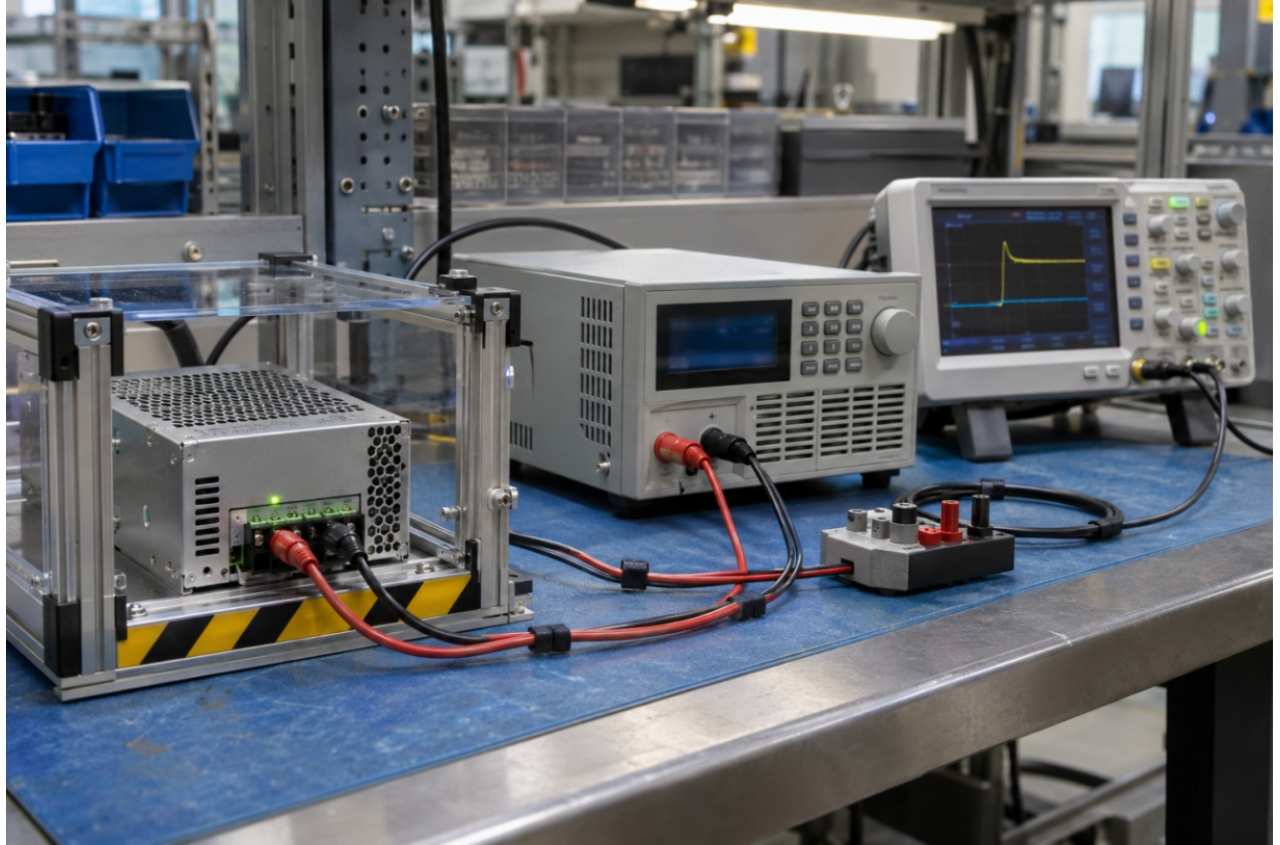
A power supply that shuts down during an overvoltage test has demonstrated one behavior. It has not yet shown that it trips at the correct voltage, limits the peak seen by the load, or restarts as intended. For production engineers, those differences determine whether a passing result actually meets the product specification. Effective overvoltage protection testing checks the complete sequence—from a controlled fault to a verified recovery.
The following six checks provide a framework for building an OVP test sequence. Acceptance limits, fault conditions, and test coverage must come from the approved product specification and validation plan.
Before Overvoltage Protection Testing Identify the Protection Behavior
Overvoltage protection (OVP) responds when a monitored voltage exceeds its specified limit. Short-circuit protection responds to an output fault that typically causes high current and a voltage collapse. Passing one test does not demonstrate that the other protection function works.
The expected response also depends on the circuit. OVP may shut down switching, disconnect a power path, clamp voltage, or activate a crowbar. Its recovery may require a reset or occur automatically. TI’s TPS2663 family, for example, includes different overvoltage cutoff and clamping variants, with recovery behavior dependent on the device and fault mode. Identify the exact configuration before defining a pass. TI TPS2663 datasheet
Current foldback belongs in the current-protection discussion: it reduces output current as output voltage falls under overload or short-circuit conditions. It should not be treated as a universal OVP topology. Toshiba’s explanation of foldback current control
1. Confirm That the Fault Exercises the Intended Protection Path
The first check in overvoltage protection testing is whether the stimulus exercises the intended protection path. Increasing the load until the output voltage collapses generally exercises current limiting or overload protection. That result does not establish an OVP trip point.
Use an OVP test method approved for the specific design. Depending on the circuit, this may involve a dedicated test interface, controlled manipulation of the feedback path, or a defined overvoltage applied to the monitored power path.
Document where the fault is applied and define the stimulus range, ramp rate and duration together with the source impedance and current limit. These conditions determine how the circuit is stressed and which parts of the protection path the test exercises, so the coverage statement should refer to the actual setup.
A signal injected directly into a comparator input may verify its threshold and downstream shutdown action while bypassing the sensing divider. It therefore needs a clear coverage statement. Likewise, raising a supply’s input voltage does not necessarily produce output overvoltage in a regulated converter.
For short-circuit testing, specify the short location, fixture resistance, switching device, and wiring. A short at the power supply terminals and one at the far end of a harness represent different fault conditions.
2. Measure the OVP Trip Point Against a Defined Window
In OVP testing, “output off” is a functional observation. The OVP trip point is a measured value with an acceptance window.
For illustration, if an approved requirement specifies a threshold of 58.0 V ±0.5 V, a trip at 58.7 V falls outside that window—even if shutdown occurs. These values are examples, not recommended limits.
For the overvoltage protection test, define whether the requirement refers to output voltage, a remote-sense point, or a voltage at a protection input. When using an injected signal, document how it relates to the specified voltage and which circuit elements the measurement includes.
Control the ramp or step sequence, settling time, starting temperature, input condition, and load. A measured dynamic trip level can differ from a slowly measured threshold because of filtering and response delay.
Measurement resolution alone is insufficient. The decision rule should account for instrument accuracy, source accuracy, fixture effects, and repeatability.
During design validation, perform OVP testing across relevant input, load, and temperature combinations. Select conditions from the circuit’s expected failure mechanisms; minimum and maximum line and load do not automatically capture every worst case. Production testing can use a validated subset where the control plan permits it.
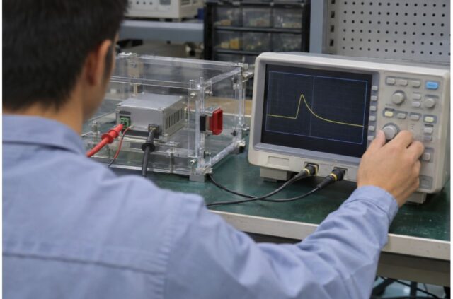
3. Capture Response Time and Peak Voltage at the Load
In an overvoltage test, a correct trip threshold does not establish how much voltage reaches the protected load before the circuit responds.
During overvoltage protection testing, record the output waveform at the relevant load connection. Where needed, also capture the monitored fault signal, current, and protection-status or switching signal. Select the channel count around the measurements required, rather than prescribing four channels for every test.
Measure the delay between threshold crossing and the start of protective action, then assess the peak voltage at the load and how long the waveform remains outside the permitted voltage envelope. Together, these measurements describe the voltage exposure before the circuit reaches its specified protected state. Record the time taken to reach that state as well, using the timing markers and limits defined in the test specification.
For a shutdown design, separate detection and switching delay from output-capacitor discharge. A lightly loaded output may remain charged after switching has stopped.
For a clamping or crowbar design, evaluate the relevant current and energy limits as well as voltage. If fuse operation is part of the protection strategy, verify its coordination through the approved validation procedure.
Choose the oscilloscope and probes for the fastest feature that matters, including overshoot and ringing. Event duration alone does not determine bandwidth requirements. A 2 µs event does not, by itself, make a 20 MHz probe unsuitable. Tektronix bandwidth and rise-time guidance
4. Verify Behavior While the Fault Remains Present
For the persistent-fault OVP test, keep the fault applied for the specified duration and observe the resulting state.
A latch-off design should remain off until its defined reset condition occurs. An automatic-retry design should follow its specified retry behavior. A clamping circuit must remain within its permitted operating conditions or transition to the next protective state as designed.
For a retrying system, record the pulse amplitude, on-time, off-time, and any change as temperature rises. A protection function can operate correctly on the first event yet behave differently during a persistent fault.
Thermal and component-stress assessment belongs in design validation where internal measurements are available. Estimating a transistor’s event energy requires voltage across that transistor and current through it. Output-terminal voltage multiplied by output current is not generally a measure of internal transistor dissipation.
Energy measurements also need the applicable device safe operating area and thermal information. A single energy integral does not predict field life.
5. Check Recovery and Restart With the Intended Load
In the recovery stage of overvoltage protection testing, remove the fault and verify the documented recovery sequence.
For latch-off protection, apply only the specified reset action, such as an enable transition or input power cycle. Check that the unit does not restart unexpectedly before that action.
For automatic recovery, confirm that the output returns within the specified conditions and timing. Capture restart overshoot, settling behavior, and any repeated trips.
Include representative load capacitance and startup demand in the OVP test setup. Restarting into a capacitive load matters after both OVP and short-circuit events; it is not exclusive to short-circuit protection.
A restart failure may indicate an interaction between soft start, current limiting, the load, and the reset sequence. Record the behavior before assigning a cause.
6. Confirm Repeatability and Recheck Normal Operation
Repeat the overvoltage protection test according to the approved validation or production plan. There is no universal requirement for five OVP events or ten short-circuit events.
Define the event count, fault duration, interval between events, starting temperature, and cooling conditions. Then check for changes in threshold, response, recovery, and normal operation.
Separate routine production checks from tests that consume a fuse, exceed normal operating stress, or may damage the unit. Such tests need a designated validation sample and an explicit disposition plan.
Test order also matters. Stress testing can change temperature and subsequent measurements, so specify stabilization and post-test checks. Do not assume that a unit remains suitable for shipment simply because it resumes operation.
Apply the Six Checks Separately to Short-Circuit Protection
The same framework can organize both tests, but each needs its own stimulus and acceptance criteria.
| Check | Overvoltage protection | Short-circuit protection |
| Fault application | Defined voltage fault or approved injection method | Defined short location, impedance, and switching method |
| Threshold | Specified OVP voltage window | Specified current threshold, where applicable |
| Dynamic response | Peak voltage, response delay, exposure duration | Peak current and transition to the protected state |
| Persistent fault | Required shutdown, clamp, or retry behavior | Required limiting, shutdown, or hiccup behavior |
| Recovery | Correct reset and restart sequence | Correct recovery with the specified load |
| Repeatability | Stable protection behavior and post-test operation | Stable protection behavior and post-test operation |
A hard short does not necessarily provide the same information as a controlled current-limit sweep. Keep those test objectives distinct.

Turn OVP Test Results Into Production Decisions
For overvoltage protection testing, record failure modes separately: threshold out of range, excessive peak voltage, delayed response, unexpected restart, or failure to recover.
These results guide investigation, but they do not identify a faulty component by themselves. An early trip could involve the DUT, fixture, stimulus, or measurement chain. Rework or trimming should follow an approved process and include the required retest.
For traceable OVP testing, retain the product identifier, test-program revision, fixture identification, operating conditions, fault method, measured results, and applicable limits. Store waveform evidence where required.
JETTEST’s power supply load testing solutions cover load modules and complete burn-in configurations. When planning overvoltage protection testing alongside these systems, specify the additional fault-generation, measurement, and control requirements. A load or burn-in configuration alone does not establish complete OVP test coverage.
To review a production test configuration, discuss your testing requirements with JETTEST. Provide the DUT ratings, protection architecture, acceptance limits, reset behavior, load characteristics, and target cycle time.