Every DC power supply produces some AC ripple on its output. It’s a fact of life in switch-mode power conversion. The rectifier and filter capacitors smooth the raw DC, but they can’t eliminate the switching artifacts entirely. The question is how much ripple is acceptable and how to measure it in a way that gives you useful, repeatable data.
Ripple voltage is the small AC component superimposed on the DC output. It’s typically measured in millivolts peak-to-peak and has two components: the fundamental switching frequency for modern power supplies and higher-frequency noise from the switching transitions. The distinction matters because a power supply might have 30 mVpp of fundamental ripple but 80 mVpp of high-frequency noise, and the two require different filtering approaches.
What causes output ripple
In a switch-mode power supply, ripple originates from the switching action of the power transistors. Each time the switch turns on, energy flows into the output inductor and capacitor. When it turns off, the inductor continues to deliver current through the freewheeling diode. The resulting voltage waveform has a triangular or sawtooth shape at the switching frequency, with the amplitude determined by the inductor value, the switching frequency, the output capacitance, and the capacitor’s ESR.
For a power supply switching at 100 kHz with a 10 μH output inductor and 1,000 μF output capacitance, the theoretical ripple is roughly 10 to 20 mVpp at full load. In practice, the ripple is higher because the capacitor’s ESR adds a voltage step whenever the current changes direction. A capacitor with 10 mΩ of ESR at 5 A of ripple current contributes an additional 50 mVpp to the output.
Beyond the fundamental switching ripple, there is broadband noise from the switching transitions. When the MOSFET turns on and off at tens or hundreds of volts in a few nanoseconds, the high dV/dt couples through parasitic capacitance in the transformer and the PCB layout. This noise appears as voltage spikes at the switching edges, typically a few nanoseconds wide and tens of millivolts high.
How to measure ripple correctly
Measuring ripple sounds straightforward — grab an oscilloscope, connect a probe across the output, and look at the waveform. But the way you connect that probe dramatically affects what you see.
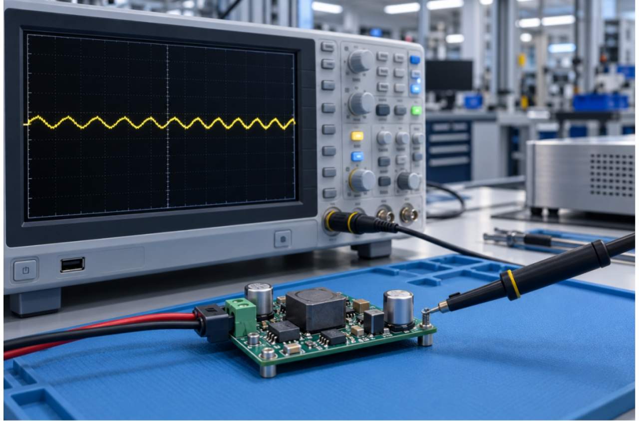
The ground lead on a standard 10× oscilloscope probe acts as an antenna. At the switching frequencies used in modern power supplies, a long ground lead picks up enough radiated noise to double or triple the apparent ripple reading. The fix is simple: remove the probe’s ground lead and clip-on tip, and use the probe’s built-in ground spring instead. This reduces the ground loop area to a few square millimeters and gives you a measurement that reflects the actual ripple rather than the noise picked up by the probe.
The measurement bandwidth matters too. Power supply testing standards typically specify a 20 MHz bandwidth limit on the oscilloscope. This filters out high-frequency noise that isn’t part of the power supply’s output ripple but can obscure the measurement. A reading taken at full bandwidth might show 100 mVpp when the actual ripple at 20 MHz bandwidth is 40 mVpp.
AC coupling is another essential setting. With DC coupling, the oscilloscope displays the full DC output voltage with the ripple superimposed. At a 12 V output, the ripple is only a fraction of a percent of the total signal, making it hard to see. AC coupling removes the DC component and amplifies the AC signal, giving you a clean view of the ripple waveform.
The measurement point matters. Ripple measured at the power supply’s output terminals is always lower than ripple measured at the load, because the output cable has impedance. For production testing, the standard is to measure at the output terminals with a specified load current. For system-level validation, measure at the load with the actual interconnect cabling.
Using a coaxial cable instead of a probe can further reduce noise pickup. A BNC cable connected directly to the output terminals through a DC blocking capacitor provides the lowest-noise measurement path. This is the standard method in automated test equipment where the measurement is performed by a dedicated ripple measurement module rather than a general-purpose oscilloscope.
What ripple levels are normal
There’s no universal acceptable ripple level — it depends on the application. But industry guidelines provide useful benchmarks. For general-purpose DC power supplies powering digital logic, less than 50 mVpp at full load is typical. For sensitive analog circuits and precision measurement equipment, less than 10 mVpp is expected. For server and telecom power supplies, less than 100 mVpp at the output terminals is standard. For battery chargers, less than 200 mVpp is acceptable since batteries tolerate higher ripple, though excessive ripple reduces battery life. For LED drivers, less than 300 mVpp is common, though visible flicker requires much lower levels.
These are guidelines, not hard limits. The actual requirement depends on what the power supply is feeding. A microcontroller with on-chip voltage regulation can tolerate more ripple than a precision operational amplifier. The key is to know your load’s ripple sensitivity and set the acceptance threshold accordingly.
What excessive ripple tells you
When ripple exceeds the expected level, it’s a diagnostic signal. The three most common causes, in order of likelihood, are:
**Aging or failing output capacitors.** The output filter capacitors in a switch-mode power supply reduce ripple by providing a low-impedance path for the AC component. As capacitors age, their ESR increases and their capacitance decreases. A capacitor with double its original ESR produces roughly double the output ripple. This is the most common cause of rising ripple in aging power supplies and the reason burn in testing includes ripple measurement at intervals.
**Inadequate input filtering.** Ripple doesn’t always come from the output stage. If the input filter capacitors are undersized or failing, the rectifier ripple at twice the line frequency couples through the switching stage and appears on the output. This shows up as a low-frequency ripple component riding on the higher-frequency switching ripple. It’s easy to miss if you’re only looking at the high-frequency content.
**Poor layout or feedback loop instability.** The control loop that regulates the output voltage has a limited bandwidth. If the loop becomes marginally stable due to component variation or layout parasitics, it can oscillate at frequencies unrelated to the switching frequency. This shows up as unexpected ripple at a frequency that doesn’t match the switching harmonics. It’s less common than capacitor issues, but harder to diagnose.
Ripple in automated production testing
During quality inspection, ripple measurement needs to be fast, repeatable, and automated. Operators don’t have time to connect an oscilloscope probe with a ground spring and set up AC coupling for every unit. The test system has to do it consistently.
In power supply burn-in testing systems, ripple is typically measured at multiple points during the burn-in cycle — at the beginning, at intervals during the test, and at the end. The trend in ripple over time is more informative than any single snapshot. A power supply whose ripple stays stable through six hours of burn-in is healthier than one that starts low but creeps up over the test duration.
Modern automated test systems integrate the oscilloscope or a dedicated ripple measurement module into the test architecture. The measurement settings — bandwidth limit, AC coupling, probe configuration — are standardized and applied automatically. The pass/fail decision is based on both the absolute ripple level and the change from the beginning to the end of the test.
For power supplies that will be used in sensitive applications like medical equipment or precision instrumentation, the ripple requirement is often specified at a particular frequency — for example, less than 10 mVpp in the 0 to 100 kHz range. The test system must be configured to apply the appropriate bandpass filter and measure only within the specified range.
Reducing ripple through design and testing
If your power supply’s ripple exceeds specifications during production testing, the fix usually involves the output stage. Increasing the output capacitance, using capacitors with lower ESR (such as polymer electrolytic or ceramic capacitors), or adding a post-filter LC stage all reduce ripple. The trade-off is cost and board space.
Layout changes can also help. Keeping the output capacitor close to the load, using a dedicated ground plane for the output return, and separating the output path from the switching node all reduce the noise coupled into the output voltage. These are design-level fixes that become apparent during pre-production validation.
For manufacturers who need to validate ripple performance without slowing down the line, the fully automatic PCBA ICT/FCT test system from Jettest can include a ripple measurement station as part of the functional test sequence. The system measures ripple at the rated load, logs the result, and flags units that drift outside the specification limits.
Turning ripple into a process signal
Ripple voltage is one of the most informative measurements you can make on a power supply. It tells you about the health of the output stage, the quality of the capacitors, and the stability of the control loop. Measured correctly — with a ground spring, 20 MHz bandwidth limit, and AC coupling — it provides a reliable pass/fail criterion for production testing. Measured carelessly, it’s a source of false failures and wasted time. Invest in the right measurement setup, and ripple becomes a diagnostic tool rather than a production headache.